

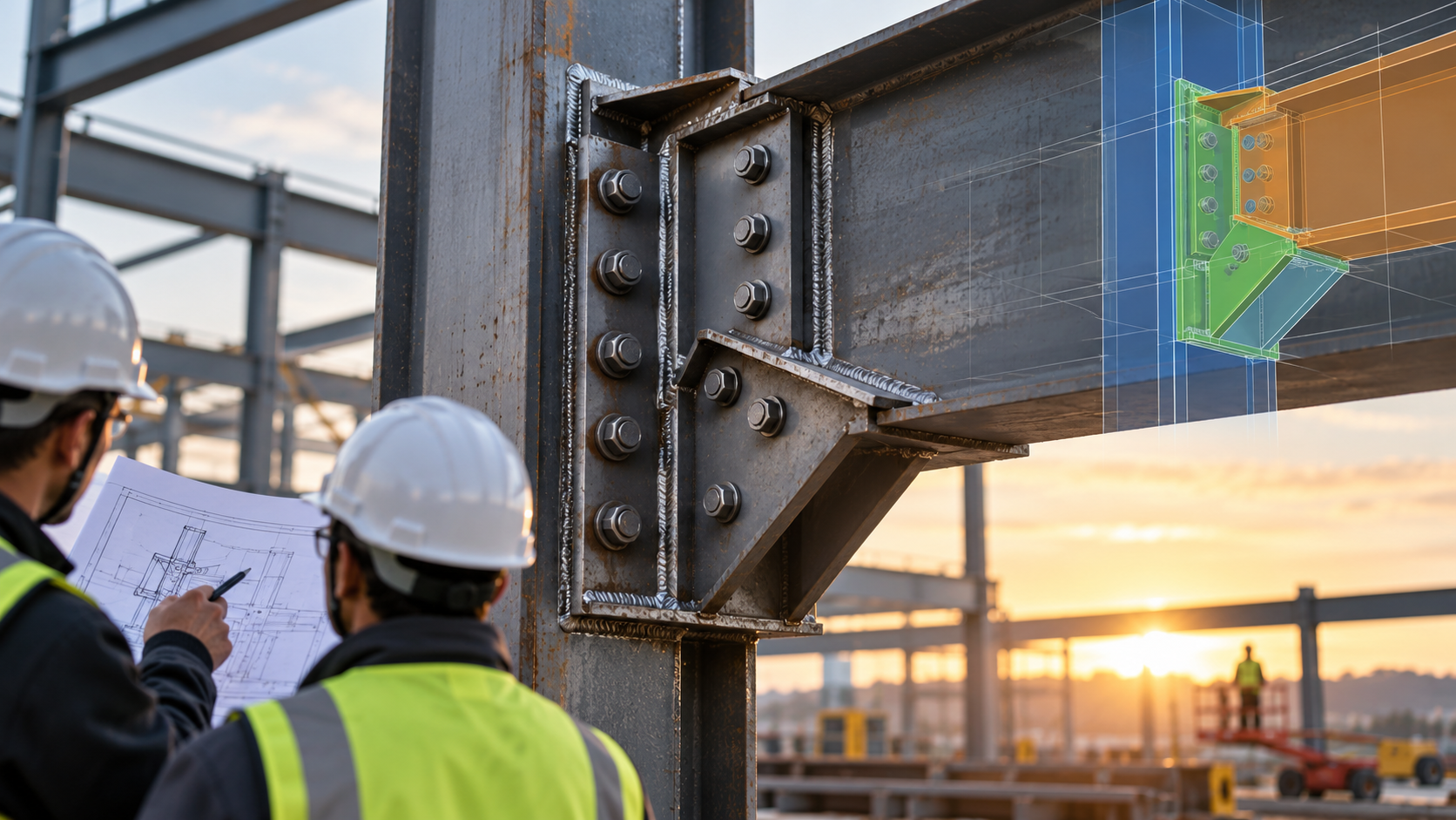
Poor Connection Detailing: 6 Hidden Costs That Drain Steel Budgets
A steel connection can appear minor on a general arrangement drawing. In the fabrication shop, however, one misplaced bolt group or inaccessible weld can interrupt an entire production sequence. Poor connection detailing rarely affects only one plate. It can trigger rework, delayed shipments, additional RFIs, and erection problems that consume a fabricator’s margin.
For example, an otherwise correct shear tab may clash with a nearby brace gusset after final framing revisions. If the shop produces both pieces before the clash is identified, the team faces two corrections: revised documentation and a physical repair that still requires engineering authorization.
The most expensive mistakes are often the ones discovered after material has been cut. Here are six costs worth identifying before connection details leave the modeling team.
1. Recut Plates and Scrapped Material
Incorrect hole locations, plate thicknesses, edge distances, or cope dimensions can make fabricated components unusable. Repair may require new material, additional cutting, drilling, or replacement assemblies. On projects with repetitive connections, one unchecked modeling error can spread across dozens of members.
Prevention: Check representative connection families and their exceptions before releasing shop drawings or CNC information.
2. Lost Shop Capacity
Rework consumes more than material. Fitters, welders, machine operators, and quality inspectors must revisit work that should already be complete. Production slots are disrupted, and the next assembly may wait for a corrected drawing or approved repair.
Prevention: Review connection geometry against fabrication methods, tooling clearances, and the shop’s standard details early.
3. Expensive Field Modifications
A connection that fits digitally may still be difficult to install. Tight bolt access, conflicting gusset plates, obstructed weld locations, or insufficient erection clearance can force crews to stop and seek direction. Field drilling or welding must not become an improvised substitute for approved details.
Prevention: Review bolt insertion, wrench access, welding access, and erection sequence with the fabricator and erector before fabrication.
4. Schedule Delays That Spread Beyond Steel
One unresolved bracing connection can hold up a lift, a bay, or follow-on trades. Crane availability, crew utilization, deliveries, and downstream activities may all be affected. The commercial impact can exceed the value of the misfabricated steel itself.
Prevention: Prioritize connections on the erection critical path and close open RFIs before releasing affected assemblies.
5. Additional Reviews and Change Management
Ambiguous connection responsibility can cause repeated submissions between detailers, fabricators, engineers, and contractors. The AISC Code of Standard Practice, ANSI/AISC 303-22, provides a framework for connection information and approval documents. Detailing teams should not independently change engineered requirements without the appropriate review and authorization.
Prevention: Maintain a connection-design responsibility matrix, drawing status register, and documented approval trail.
6. Quality and Client Confidence Risks
Incorrect weld symbols, incomplete bolt callouts, or inconsistent revisions can create inspection findings and undermine confidence in fabrication documentation. AWS D1.1/D1.1M:2025-AMD1 covers structural steel welding requirements where specified by the project. The applicable contract edition must always be checked.
Prevention: Run an independent QA/QC review of welds, bolts, material grades, dimensions, and drawing-to-model consistency.
Build a Connection-Detailing Gate Before Release
A reliable release process connects the design team with shop and field requirements:
- Confirm inputs. Resolve missing reactions, design criteria, specifications, and connection-design responsibility.
- Model constructability. In SDS2 or the designated platform, check clashes, connection geometry, clearances, and piece orientation.
- Verify interfaces. Coordinate anchors, embeds, adjacent trades, tolerances, and site access with the responsible parties.
- Control issue status. Release only drawings approved for their intended purpose, with revision records linked to affected assemblies.
Track first-pass drawing approval, connection-related RFIs, shop rework hours, and field modification requests. These measures reveal whether detailing quality is protecting actual project performance, not merely drawing throughput.
Conclusion
Connection detailing is a cost-control activity, not simply a documentation task. Detecting a bolt-access problem in a model is more manageable than discovering it with a crane waiting on site.
At Steel Step Solutions, SDS2-based 3D modeling and fabrication-ready detailing help project teams review connections, coordinate interfaces, and identify constructability concerns before steel reaches the shop.